Tuned circuits
A beginner's guide to tuned circuits.
Scope
This article aims to give the reader an overall idea of the use of tuned LC circuits, and the theory behind them. The article is especially written for people who collect and restore vintage radios.
Self-induction
To understand tuned circuits, we first have to understand the phenomenon of self-induction. And to understand this, we need to know about induction.The first discovery about the interaction between electric current and magnetism was the realization that an electric current created a magnetic field around the conductor. It was then discovered that this effect could be enhanced greatly by winding the conductor into a coil. The effect proved to be two-way: If a conductor, maybe in the form of a coil was placed in a changing magnetic field, a current could be made to flow in it; this is called induction.
So imagine a coil, and imagine that we apply a voltage to it. As current starts to flow, a magnetic field is created. But this means that our coil is in a changing magnetic field, and this induces a current in the coil. The induced current runs contrary to the applied current, effectively diminishing it. We have discovered self-induction. What happens is that the self-induction delays the build-up of current in the coil, but eventually the current will reach its maximum and stabilize at a value only determined by the ohmic resistance in the coil and the voltage applied. We now have a steady current and a steady magnetic field. During the buildup of the field, energy was supplied to the coil, where did that energy go? It went into the magnetic field, and as long as the magnetic field exists, it will be stored there.
Now imagine that we remove the current source. Without a steady current to uphold it, the magnetic field starts to disappear, but this means our coil is again in a variable field which induces a current into it. This time the current is in the direction of the applied current, delaying the decay of the current and the magnetic field till the stored energy is spent. This can give a funny effect: Since the coil must get rid of the stored energy, the voltage over it rises indefinitely until a current can run somewhere! This means you can get a surprising amount of sparks and arching when coils are involved. If the coil is large enough, you can actually get an electric shock from a low-voltage source like an ohmmeter.
Self-inductance is measured in henry (H or Hy). A henry is almost as enourmous value as a Farad, and coils are often measured in milli, micro and even nanohenry.
Now to tuned circuits
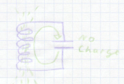
So, a coil is a component that effectivily stores current. A capacitor is a component that stores voltage. If we connect those two together, we get interesting results. Imagine a coil (L) and a capacitor (C) connected in parallel:
Let us assume we charged the capacitor with a voltage before connecting it to the coil, so now we apply that voltage to the coil. This means a current starts to flow, and a magnetic field is created. As the magnetic field builds up and reaches maximum, an increasing amount of current flows in the circuit. Eventually, the capacitor becomes discharged; the voltage across it is zero, but now a magnetic field has been built in the coil and a current is flowing in the circuit, the charge has been transferred and transformed: From a voltage charge in the capacitor to a current charge in the coil.
As the voltage is now gone, the current starts to decay, but the self-induction keeps it running till the magnetic field has been spent. This current charges the capacitor, now with the opposite polarity as before; the charge is transferred back to the capacitor:
When the current stops, the voltage starts a new current in the opposite direction, etc. etc. The charge swings like a pendulum back and forth between the coil and the capacitor, changing polarity twice in each cycle. If there were no losses, this would go on forever. In real life, some energy is lost in each cycle, and unless the lost energy is somehow replaced, the tuned circuit will ring out, much like a bell:
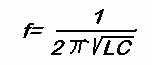
Like a pendulum, the tuned circuit swings at a certain frequency, here determined by the values of the components. The formula is simple:
Types of tuned circuits
Many variations and complex couplings exist, but there are just two basic couplings, series and parallel:
The parallel circuit has its highest impedance at the
resonance frequency. Placed across a signal, it allows only the resonance frequency to
pass.
The series circuit has its lowest impedance at the resonance frequency. Placed across a
signal, it shorts out the resonance frequency, allowing all other frequencies to pass.
Bandwidth
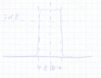
Of course nothing is as simple as it seems. The tuned circuit has a bandwidth, that is, frequencies near the actual resonance frequency will also more or less achieve resonance. The bandwidth curve of a single resonant circuit looks like this:
The width of this curve depends on the Q parameter of the circuit. The Q is basically a figure for the effectivity of the tuned circuit. A circuit with a high loss will have a low Q and a high bandwidth. A circuit with low losses will have a high Q and a narrow bandwidth. Losses come mostly from two things:
Coupled resonance
In complex circuits like radios, the simple resonant curve of one tuned circuit is not always enough. To transmit the frequency range needed for audio, a bandwidth of at least twice the audio range is needed, but outside that a steep rolloff is needed. For this purpose several sets of tuned circuits coupled together in a so-called critical coupling is used, like in IF transformers. Two critically coupled tuned circuits have a resonance curve that looks like this:
Various couplings can be encountered, forming low-pass, high-pass, band-pass or band-suppression filters, but these specialized circuits are beyond the scope of this article.
Other types of resonant circuits
There are other types of components than coils and capacitors that can form resonant, or tuned, circuits. Most radio interested people have encountered the crystal. Made of quartz or some other piezo-electric material, the crystal forms a tuned circuits all by itself. The main characteristics of crystals are:
Complex filters can be built from crystals and other piezo-electric components, giving characteristics unattainable with RC circuits. In older radio equipment, such components were only affordable in professional or semi-professional gear, but lower component costs, new materials and rising labour costs have made them find their way into most modern receivers, even in the low-price bracket.
Hans Egebo