Receiver Technology
Various interesting details in receiver technology
Prerequisite
The reader is assumed to be familiar with the basic superheterodyne principle.
General
The superheterodyne principle, which is the basis for the vast majority of all radio receivers built since the early nineteen thirties, is quite simple and straight-forward, once you understand it. However, as always, there is more to things than immidiately meets the eye. This article will discuss various concepts that it will be helpful to understand if you want to repair or restore radio receivers. The article is aimed at readers who are interested in restoring vintage radios, and although the basic principles apply to all technologies, this article will be centered around traditional tube technology.
Automatic Gain Control, AGC
In the article about the basic Superheterodyne Principle, this simplified receiver schematic was shown:
This circuit may function, but it has a problem: The signal strengths of different stations is bound to vary greatly; not only can the transmitter power be different, but medium wave permits you to receive stations from an entire continent, and the signal received from a distant transmitter will be several orders of magnitude weaker than that from one close by. This will give raise to a whole host of problems: Not only will the audio output of our receiver vary according to the input signal, but if a strong signal drives one or several of the amplifier stages to saturation, several unwanted effects will occur, including distortion, spurious signals, intermodulation, etc. etc. So we need to be able to regulate the overall gain in our receiver, and since the user scanning the broadcast band has no way of knowing what signal strength to expect next, this regulation should preferably be automatic. Fortunately, an automatic gain control (AGC) is not too difficult to implement.
We already have a detector which rectifies the signal. The detector has a time-constant that enables the output to follow the audio signal, but if we add an RC circuit with a longer time-constant, we get a DC voltage that is equivalent to the signal strength. For any tube, the more negative control grid bias you give it, the lower gain will it have. Tube types used in mixer and IF amplifiers are optimized for this, so by feeding the signal dependant DC voltage to the bias circuit of the tubes, you can make a system with a gain that is inversely proportional to the input signal strength. In other words, despite great variation in input signal, the output signal will be fairly constant. We have invented AGC.
That was the theory, now for the practical implementation
In many receivers, a separate rectifier is used for the AGC, but here we go for the simple, and use the detector. Previously, our detecter produced a positive voltage, but we need a negative one, so we have to change the circuit a little bit. This has no impact on audio detection, but we need an extra RC circuit with a long time-constant for the AGC, call it a filter if you will. Now, our detector looks like this:
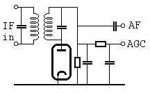
The position of the rectifier diode may surprise you. Why dont we just invert the connection to it to get a negative output? Well, we might, but in real life, these diodes are rarely an independent tube. Instead they are part of a double or even triple-function tube. These multiple systems often share the same cathode, so we are not at liberty to connect them as we please; this is the reason for the grounded cathode approach.
Next we need to modify our mixer- and IF stages to enable us to regulate their bias voltages. This is a tad more complex than you might think, espeially in the IF stage, because this tube is entirely self-biasing. This means that the current flowing in the tube creates the bias voltage acros a resistor inserted at the cathode. Our AGC regulation will change the current running in the tube, and in effect this will counteract the regulation. So we need to get a fixed bias voltage for this tube; in this case we "borrow" some bias voltage from the cathode of the output tube. The mixer tube shares its bias resistor with the oscillator tube, and in this case we shall deem this sufficient, but you will see schematics where this bias is also aquired elsewhere.
Finally, our grid circuits need modification. In the simple version, grids were simply unloaded through the coils, now we have to insert a coupling capacitor and a resistor to each grid. So now our schematic looks like this:
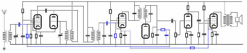
The new or changed parts are shown in blue
A few more additions
In our schematic, the B+ supply is simply wired to all stages. This is a rather daring approach which is likely to cause various problems in real life. One of the most important considerations is hum. One of the important sources of hum in an AC powered radio is ripple on the DC voltages. Even though the rectified voltage is filtered, some ripple will remain. The output stage is quite tolerant to ripple; the current in the output tube is only partly dependant on the B+ voltage, and there is no voltage amplification, so several volts of ripple might be tolerated here. Not so with the earlier stages: The AF amplifier tube, a triode, has poor riple suppression capabilites, and any ripple introduced at this stage will get amplified by the output stage. The RF and IF stages are a bit more tolerant in themselves, but with the much higher subsequent amplification, they also become critical. There are other problems as well, but to make a long story short, we need extra filtering in the B+ for the early stages in our radio. Fortunately, these circuits dont draw a lot of current, so simple RC filters will do the job. One more thing: Because of the capacitance values needed, some of the capacitors in a radio will be of the electrolytic type. This type has limited lifetime, so when repairing or restoring old radios, electrolytics often need changing. In the schematic below, electrolytic capacitors are shown in the positions where you will normally find them:
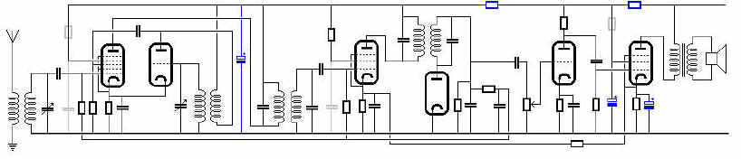
As you can see, the cost in extra parts is not as high as could be expected, since the better filtering alows us to do away with some screen-grid resistors and -filters. Added parts and connections are shown in blue, removed parts in light gray.
Power supplies
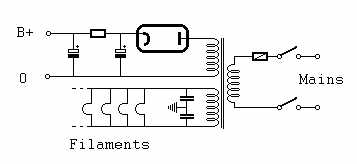
Tube radios can be run on batteries, but mostly they are supplied from the mains. In all parts of the industrialized world to-day, the mains carries AC, but in Europe, DC could be still be encountered as late as 1965. The most straight forward way to build a power supply is using AC. Tubes need at least two voltage sources, one for the filament and a B+ voltage. Different filament voltages can be found, but many modern types run on 6.3V AC. B+ must be a DC voltage and a normal radio will require 100-250V. Using a transformer and a rectifier tube, it is simple to make a power supply for our radio:
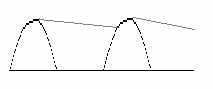
This is called a half-wave rectifier, because it only uses one half of the sinus wave:
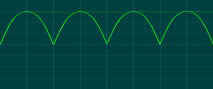
The drawback is that this approach requires a fairly large filter capacitor. At the cost of an extra rectifier and an extra transformer winding, we can get a full-wave rectifier with more modest filtering requirements:
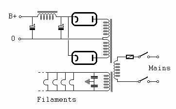
Which to choose is a matter of trade-off. Generally, for low current requirements, you will see the single rectifier, whereas large power supplies will favor the full-wave rectifier. Note that a choke is used in the filter here; the choke has low DC resistance and high AC resistance (because of induction), so this is an effective, if more expensive filter solution.
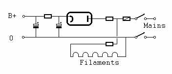
And in both, the filament circuit: All tube filaments will generally be connected in parallel across a low-voltage winding. Sometimes you will see the filament winding grounded via a center tab or two capacitors (shown here); this is to suppress hum. Some types of rectifier tubes have direct-heated filaments, and as the rectifier chatodes are at B+ potential, this requires a separate filament winding. Note that the parallel heater configuration requires all the tubes to use the same filament voltage, e.g. 6.3V. Different types of tubes may draw different filament currents.
But I mentioned that lots of consumers had DC in their outlets till the very end of the tube era, and with DC, use of transformers is difficult (not impossible, you have to in e.g. car radios), instead the so-called "universal" supply type is often used. In fact, the vast majority of European radios produced between 1930 and 1960 are of this type.
A few things are notable here:
In this type of power supply, a full-wave rectifier can only be implemented by using four rectifiers coupled as a rectifier bridge. This only became practical when solid-state rectifiers became available, but in equipment from the middle fifties and newer, you will often find a selenum bridge rectifier. Even later, silicon diodes were used.
In this type of power supply, you will often find a special component in the filament chain (not shown in the schematic above): An NTC resistor. NTC stands for Negative Temperature Coefficient. In a series filament chain, hotspots can easily occur; imagine one of the filaments, or part of it, heating up faster than the rest. A filament has a positive temperature coefficient, that is, the hotter it gets, the greater resistance it has. Now, the filament part that is hotter than the rest gets greater resistance, and while this does not change the total resistance, and thus the current, much, the voltage drop over that particular part will rise, and with that, the power dissipated in it, so it will get hotter, so more voltage drop, more power, -- and we have a hotspot, and potential destruction. The NTC has a large resistance when cold, so it takes most of the voltage drop, then as it heats up, its resistance drops, and the voltage drop is transferred to the filaments. This soft start gives them time to heat up more equally.
Replacing rectifier tubes with silicon diodes
When repairing or restoring old radios, it may be tempting to replace a faulty rectifier tube or selenum rectifier with a cheap, rugged modern silicon diode. This can be done, but there are a few things to consider:
Hans Egebo